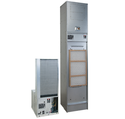
Vertical Stack Units – 0.75 to 3 tons
The Tranquility® Vertical Stack (TSM) Series offers an innovative, labor-saving solution for spaces with little or no ductwork and where individual, quiet control of the heating and cooling system is important. Using EarthPure® (HFC-410A) refrigerant, the Tranquility® Vertical Stack (TSM) Series not only protects the environment, it does so while delivering unprecedented comfort, efficiency, and reliability.
- Sizes 09 (¾ ton, 2.6 kW) – 36 (3 ton, 10.6 kW)
- Environmentally-friendly EarthPure® (HFC-410A) zero ozone depletion refrigerant
- High-efficiency rotary & scroll compressors
- Exceeds ASHRAE 90.1 efficiencies
- Removable chassis allows staged installation & ease of maintenance
- Galvanized steel cabinet
- Unique double isolation compressor mounting for quiet operation
- TXV metering device
- Unit or remote-mounted controls available
- Optional ECM motor cabinet can slide over riser ball valve easily — this allows riser stack to be completed first
- Microprocessor controls standard or optional DXM2 control. Both available with ECM motors
- Available with constant torque or constant volume ECM motors
- LonWorks, BACnet, Modbus & Johnson N2 compatibility options for DDC controls
- Sentinel performance monitoring system
- Attractive return air panel with hinged access door (“G” panel)
- Aesthetically pleasing flush mounted return air panel ("L" panel)
- Multiple supply air discharge options
- Optional field convertible or factory configured supply air openings
- Stainless steel braided hose kits for connection from piping risers to chassis
- Options for both auto flow regulators and motorized water valves
- Optional, industry first modulating motorized water valve
- 8 safeties standard
- Wide variety of options including disconnect switch & extended range
- 3 footprint sizes
- Advanced digital controls with Remote Service Sentinel. Shown with optional DDCcontroller. Optional enhanced controls (DXM2) also available.
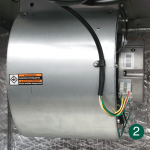
- Torsion-flex blower motors TSM09-12.
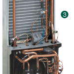
- Exclusive dual compressor vibration isolation lowers vibration & reduces noise for quiet operation. Removable chassis allows staged installation & ease of maintenance/service once installation is complete.
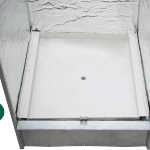
- Integrated drain pan with condensate overflow protection. Optional stainless steel insulated drain pan.
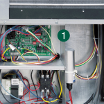
1) Control Panel
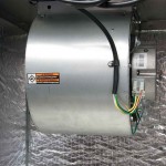
2) Blower
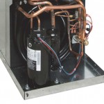
3) Chassis
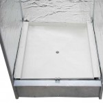
4) Drain Pan
|
|
|
T-Stat: Non-Communicating
Eletrical V/Hz/Ph | Unit Controller | Fan Motor | Water Options | Wiring Diagrams | ||
|---|---|---|---|---|---|---|
TSM 09-36 | TSM 09-12 | TSM 15-36 | ||||
208-230/60/1 | CXM2 | PSC | STD/ MWV (N.C.)/ ISP | N/A | N/A | |
MWV (N.O.) | N/A | N/A | ||||
3-Way MWV | N/A | N/A | ||||
CT ECM | STD/ MWV (N.C.)/ ISP | N/A | ||||
MWV (N.O.) | N/A | |||||
3-Way MWV | N/A | |||||
T-Stat: Non-Communicating
Eletrical V/Hz/Ph | Unit Controller | Fan Motor | Water Options | Wiring Diagrams | |
|---|---|---|---|---|---|
TSM 09-12 | TSM 15-36 | ||||
208-230/60/1 | DXM2.5 | PSC | STD/ MWV (N.C.)/ ISP | N/A | |
MWV (N.O.) | N/A | ||||
3-Way MWV | N/A | ||||
Mod Valve | N/A | ||||
CT ECM | STD/ MWV (N.C.)/ ISP | ||||
MWV (N.O.) | |||||
3-Way MWV | |||||
| Mod Valve | |||||
CV ECM | STD/ MWV (N.C.)/ ISP | ||||
MWV (N.O.) | |||||
3-Way MWV | |||||
Mod Valve | |||||
T-Stat: Communicating
Eletrical V/Hz/Ph | Unit Controller | Fan Motor | Water Options | Wiring Diagrams | ||
|---|---|---|---|---|---|---|
TSM 09-36 | TSM 09-12 | TSM 15-36 | ||||
208-230/60/1 | DXM2.5 | PSC | STD/ MWV (N.C.)/ ISP | N/A | N/A | |
MWV (N.O.) | N/A | N/A | ||||
3-Way MWV | N/A | N/A | ||||
Mod Valve | N/A | N/A | ||||
CT ECM | STD/ MWV (N.C.)/ ISP | N/A | ||||
MWV (N.O.) | N/A | |||||
3-Way MWV | N/A | |||||
Mod Valve | N/A | |||||
| CV ECM | STD/ MWV (N.C.)/ ISP | N/A | ||||
MWV (N.O.) | N/A | |||||
3-Way MWV | N/A | |||||
Mod Valve | N/A | |||||
The Tranquility® Vertical Stack (TSL) Series is the first vertical stack classified as a ducted product. It offers an innovative, labor-saving solution for spaces with ductwork and where individual, quiet control of the heating and cooling system is important. Using EarthPure® (HFC-410A) refrigerant, the Tranquility® Vertical Stack (TSL) Series not only protects the environment, it does so while delivering unprecedented comfort, efficiency, and reliability.
- Sizes 09 (¾ ton, 2.6 kW) – 36 (3 ton, 10.6 kW)
- Environmentally-friendly EarthPure® (HFC-410A) zero ozone depletion refrigerant
- High-efficiency rotary or scroll compressors
- Exceeds ASHRAE 90.1 efficiencies
- Removable chassis allows staged installation and ease of maintenance
- Galvanized steel cabinet
- Unique double isolation compressor mounting for quiet operation
- TXV metering device
- Unit or remote-mounted controls available
- Optional ECM motor cabinet can slide over riser ball valve easily — this allows riser stack to be completed first
- Microprocessor controls standard or optional DXM2 control. Both available with ECM motors
- Available with constant torque or constant volume ECM motors
- LonWorks, BACnet, Modbus & Johnson N2 compatibility options for DDC controls
- Sentinel performance monitoring system
- Attractive return air panel with hinged access door (“G” panel)
- Aesthetically pleasing flush mounted return air panel (“L” panel)
- Multiple supply air discharge options
- Optional field convertible or factory configured supply air openings
- Stainless steel braided hose kits for connection from piping risers to chassis
- Options for both auto flow regulators and motorized water valves
- Optional, industry first modulating motorized water valve
- 8 safeties standard
- Wide variety of options including disconnect switch and extended range
- 3 footprint sizes
- Wall-mounted controller available
- Choice of high efficiency ECM or PSC motor
- Short cabinet height for adding field ductwork
- Standard high static motor intended for ducted static regain
- Cabinet can slide over riser ball valve easily — this allows riser stack to be completed first
- Advanced digital controls with Remote Service Sentinel. Shown with optional enhanced controls (DXM2).
- Torsion-flex blower motors TSL09-12.
- Dual compressor vibration isolation lowers vibration & reduces noise for quiet operation. Removable chassis allows staged installation & ease of maintenance/service once installation is complete.
- Integrated drain pan with condensate overflow protection. Optional stainless steel drain pan.
1) Control Board
2) Blower
3) Chassis
4) Drain Pan
|
|
|
T-Stat: Non-Communicating
Eletrical V/Hz/Ph | Unit Controller | Fan Motor | Water Options | Wiring Diagrams | ||
|---|---|---|---|---|---|---|
TSL Ducted 09-36 | TSL Ducted 09-12 | TSL Ducted 15-36 | ||||
208-230/60/1 | CXM2 | PSC | STD/ MWV (N.C.)/ ISP | N/A | N/A | |
MWV (N.O.) | N/A | N/A | ||||
3-Way MWV | N/A | N/A | ||||
CT ECM | STD/ MWV (N.C.)/ ISP | N/A | ||||
MWV (N.O.) | N/A | |||||
3-Way MWV | N/A | |||||
T-Stat: Non-Communicating
Eletrical V/Hz/Ph | Unit Controller | Fan Motor | Water Options | Wiring Diagrams | |
|---|---|---|---|---|---|
TSL Ducted 09-12 | TSL Ducted 15-36 | ||||
208-230/60/1 | DXM2.5 | PSC | STD/ MWV (N.C.)/ ISP | N/A | |
MWV (N.O.) | N/A | ||||
3-Way MWV | N/A | ||||
Mod Valve | N/A | ||||
CT ECM | STD/ MWV (N.C.)/ ISP | ||||
MWV (N.O.) | |||||
3-Way MWV | |||||
| Mod Valve | |||||
CV ECM | STD/ MWV (N.C.)/ ISP | ||||
MWV (N.O.) | |||||
3-Way MWV | |||||
Mod Valve | |||||
T-Stat: Communicating
Eletrical V/Hz/Ph | Unit Controller | Fan Motor | Water Options | Wiring Diagrams | ||
|---|---|---|---|---|---|---|
TSL Ducted 09-36 | TSL Ducted 09-12 | TSL Ducted 15-36 | ||||
208-230/60/1 | DXM2.5 | PSC | STD/ MWV (N.C.)/ ISP | N/A | N/A | |
MWV (N.O.) | N/A | N/A | ||||
3-Way MWV | N/A | N/A | ||||
Mod Valve | N/A | N/A | ||||
CT ECM | STD/ MWV (N.C.)/ ISP | N/A | ||||
MWV (N.O.) | N/A | |||||
3-Way MWV | N/A | |||||
Mod Valve | N/A | |||||
| CV ECM | STD/ MWV (N.C.)/ ISP | N/A | ||||
MWV (N.O.) | N/A | |||||
3-Way MWV | N/A | |||||
Mod Valve | N/A | |||||
Traditional water source heat pump systems are designed for applications where there is demand for some units to be in heating while others are in cooling throughout much of the year. Hybrid water source heat pump systems outperform traditional systems by combining the best of refrigerant air conditioning and hydronic heating resulting in quieter operation and potential operating cost savings.
- Building water loop temperatures can be designed as high as 120 degrees with a hybrid water source heat pump system. This lets the system retain more of the heat generated by the heat pumps that are in the cooling mode without rejecting that heat through a cooling tower.
- Instead of using a compressor in the heating mode, the hybrid heat pump operates as a fan coil in the heating mode. This can be more cost effective than traditional water source heat pump systems based on energy costs.
- Heat utilization is maximized. With a hybrid water source heat pump system up to 100% of the outdoor air can be brought into the building using an air handler with a hydronic water coil fed by the buildings higher temperature building loop. This can prevent the scenario where you have gas heat treating outdoor air while a cooling tower rejecting heat from the building loop.
- Quiet operation during heating mode because the unit is not using a compressor to generate heat.
- Reduced compressor cycling.
- No reversing valve.
- Advanced digital controls with Remote Service Sentinel. Shown with optional enhanced controls (DXM2).
- Torsion-flex blower motors TSL09-12.
- Dual compressor vibration isolation lowers vibration & reduces noise for quiet operation. Removable chassis allows staged installation & ease of maintenance/service once installation is complete.
- Integrated drain pan with condensate overflow protection. Optional stainless steel drain pan.
1) Control Board
2) Blower
3) Chassis
4) Drain Pan
|
|
|
T-Stat: Non-Communicating
Eletrical V/Hz/Ph | Unit Controller | Fan Motor | Water Options | Wiring Diagrams | |
|---|---|---|---|---|---|
TSL Hybrid 09-12 | TSL Hybird 15-36 | ||||
208-230/60/1 | CXM2 | CT ECM | Hybrid MWV N.C. | ||
Hybrid MWV N.O. | |||||
Hybrid 3-Way Valve | 96B0434N12 | 96B0434N15 | |||
Hybrid 3-Way Valve ISP | |||||
T-Stat: Non-Communicating
Eletrical V/Hz/Ph | Unit Controller | Fan Motor | Water Options | Wiring Diagrams | |
|---|---|---|---|---|---|
TSL Hybrid 09-12 | TSL Hybrid 15-36 | ||||
208-230/60/1 | DXM2.5 | CT ECM | Hybrid MWV N.C. | ||
Hybrid MWV N.O. | |||||
Hybrid 3-Way Valve | |||||
| Hybrid 3-Way Valve ISP | |||||
CV ECM | Hybrid MWV N.C. | ||||
Hybrid MWV N.O. | |||||
Hybrid 3-Way Valve | 96B0433N25 | 96B0433N26 | |||
Hybrid 3-Way Valve ISP | |||||
T-Stat: Communicating
Eletrical V/Hz/Ph | Unit Controller | Fan Motor | Water Options | Wiring Diagrams | |
|---|---|---|---|---|---|
TSL Hybrid 09-12 | TSL Hybrid 15-36 | ||||
208-230/60/1 | DXM2.5 | CT ECM | Hybrid MWV N.C. | ||
| Hybrid MWV N.O. | |||||
| Hybrid 3-Way Valve | |||||
| Hybrid 3-Way Valve ISP | |||||
| CV ECM | Hybrid MWV N.C. | ||||
Hybrid MWV N.O. | |||||
Hybrid 3-Way Valve | 96B0433N22 | ||||
Hybrid 3-Way Valve ISP | |||||
The Tranquility® Vertical Stack (TRM) Series offers an innovative, labor-saving solution for spaces where individual, quiet control of the heating and cooling system is important. Using EarthPure® (HFC-410A)refrigerant, the Tranquility® Vertical Stack (TRM) Series not only protects the environment, it does so while delivering unprecedented comfort, efficiency, and reliability.
- Sizes 09 (3/4 ton, 2.6 kW) through 36 (3 ton, 10.6 kW)
- Environmentally-friendly EarthPure® (HFC-410A) zero ozone depletion refrigerant
- High efficiency rotary and scroll compressors
- Exceeds ASHRAE 90.1 efficiencies
- Removable chassis allows staged installation and ease of maintenance
- Galvanized steel cabinet
- Unique double isolation compressor mounting for quiet operation
- TXV metering device
- Unit or remote-mounted controls available
- Optional ECM Motor for all models
- Microprocessor controls standard (optional DXM and/or DDC controls)
- BACnet, Modbus and Johnson N2 compatibility options for DDC controls
- Unit Performance Sentinel performance monitoring system
- Attractive return air panel with hinged access door (“G” panel)
- Multiple supply air discharge options
- Stainless steel braided hose kits for connection from piping risers to chassis
- Eight safeties standard
- Wide variety of options including disconnect switch and extended range
- Advanced digital controls with Remote Service Sentinel. Optional enhanced controls (DXM) also available.
- Torsion-flex blower motors TRM09-12.
- Exclusive dual compressor vibration isolation lowers vibration & reduces noise for quiet operation. Removable chassis allows staged installation & ease of maintenance/service once installation is complete.
- Integrated drain pan with condensate overflow protection. Optional stainless steel insulated drain pan.
1) Control Board
2) Blower
3) Chassis
4) Drain Pan
|
|
|
Electrical V-Hz-Ph | Unit Controller | Options | Wiring Diagrams 817/TRM 09-36 |
|---|---|---|---|
208-230/60/1 | "P" Controls | Standard/ FC MWV | |
FO MWV | |||
"S" Controls | None | ||
"M" Controls | None |
Electrical V-Hz-Ph | Unit Controller | Options | Wiring Diagrams 817/TRM 09-36 |
|---|---|---|---|
265/60/1 | "P" Controls | Standard/ FC MWV | |
FO MWV | |||
"S" Controls | None | ||
"M" Controls | None |